|
|
|||||||||||||||||||||||
|
|
|||||||||||||||||||||||
 |
|||||
 |
|||||
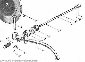
Clutch: |
|
|
||||||||||||
 |
 |
|||||
|
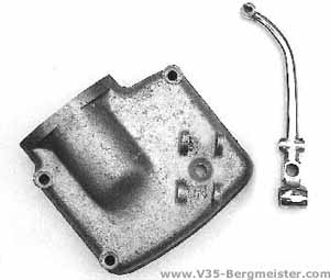
On the left the gearbox cover with the casted seat bearing for the clutch lever, used up to an engine no. of 3497. |
||||||
|
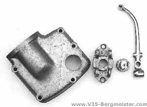
Since engine no. 3498 the clutch mechanism was completely redesigned (see picture right above and cross section below on the left). |
||||||
 |
||||||
|
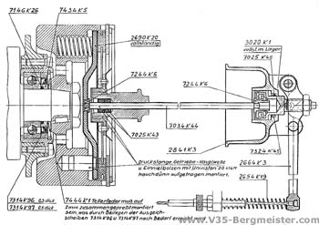
Cross section drawing taken from the Technical Bulletin No. 14 from July 1954) |
||||||